MV-1C connection problem with Retrotink 2x SCART

Sho G.

Quiz Detective
10 Year Member
Joined
Apr 30, 2011
Posts
82
Hello everyone. I am trying to connect an MV-1C with the Retrotink 2x SCART to a Panasonic Viera TV and I can't get a picture. Only a few lines of color from Retrotink itself are shown and when I turn on the Neo Geo and it sends the signal to it, the TV goes dark. I have tried all the firmware for the Retrotink and it gives me the same result.

On the other hand, when I connect the Neo Geo directly to the TV via RGB, it gives me many errors. The image is shown cropped from the left and top. To be able to connect it, I had to take the Sync cable directly because with any resistance that comes up, the screen turns dark.

Could it be compatibility issues between the Neo Geo and the Retrotink? Or could it be problems with the Sync signal from the MV-1C?

I also have to add, that I removed the SCART connector and soldered the RGB and Sync cables directly to the Retrotink.
 

prof

A Great Place to Store Your Dildo Collection
Joined
Jul 15, 2015
Posts
1,249
Are there inputs and a 240/480 switch on that model? There may be a button for line doubling as well? I have one, but I'm not sure if it's the model same as yours, they have a few different ones. If it has any settings on it though, try cycling through them. That could be the culprit.


Regardless, I can tell you that plugging an MV-1C directly into the component inputs of my old Sony Bravia HDTV from 08 or so did not work. Even though those same component inputs work fine with other consoles. The outputs works great through the Retrotink into my newer tv, but not on the old one. Audio and no picture. I tried s-video and composite, and they both worked fine going directly into the old TV though. So perhaps it's not the Retrotink. Some TVs just don't like the video signal from the MV-1C.
 

Neo Alec

Ned's Ninja Academy Dropout
20 Year Member
Joined
Dec 7, 2000
Posts
11,994
The problem is almost definitely the TV. The TV probably could be used with the MV-1C with a 1080p upscaler that can correct the sync, such as the Retrotink 5X or Framemeister.
 

prof

A Great Place to Store Your Dildo Collection
Joined
Jul 15, 2015
Posts
1,249
The problem is almost definitely the TV. The TV probably could be used with the MV-1C with a 1080p upscaler that can correct the sync, such as the Retrotink 5X or Framemeister.
Now that you mention it, I think mine is the 5x. Which would explain why component works perfectly through it into the new tv, but not into the component inputs of my old one.

My older tv has component, composite, hdmi, s-video, even a vga pc input that works great with Dreamcast. So I've got about a billion switch boxes and all the old consoles hooked up to it. But the new tv, nice as it is, is HDMI only. So I literally had to get the retrotink to get anything older than ps3 to work with it. I hate that, although I suppose it makes sense. Not many people nowadays want to hook up electronics that aren't at least HDMI.

So, yeah, Sho G. Either getting a higher end retrotink or using another tv is going to be your best bet in all likelihood.
 

maki

Edo Express Delivery Guy
Joined
Jan 1, 2022
Posts
334
I am trying to connect an MV-1C with the Retrotink 2x SCART to a Panasonic Viera TV and I can't get a picture.
Do you know if the MVS works in general?

If so, whats the connection between the MVS and Retrothink?
MVS will output TTL levels for RGBS, you needs 75Ohm levels though, is there a THS RGB amp somewhere, or just resistors?
If it is neither, it's not supposed to work IMO.
 

SignOfGoob

Butthurt Enthusiast
20 Year Member
Joined
Sep 18, 2003
Posts
2,857
I have the same Retrotink as you and can confirm 2 slot MVS compatibility is flawless. My super gun uses the Arcadeforge PCB with a SCART socket on it. Whatever they used for buffering resistors or whatever is exactly what is required.
 

Sho G.

Quiz Detective
10 Year Member
Joined
Apr 30, 2011
Posts
82
Are there inputs and a 240/480 switch on that model? There may be a button for line doubling as well? I have one, but I'm not sure if it's the model same as yours, they have a few different ones. If it has any settings on it though, try cycling through them. That could be the culprit.


Regardless, I can tell you that plugging an MV-1C directly into the component inputs of my old Sony Bravia HDTV from 08 or so did not work. Even though those same component inputs work fine with other consoles. The outputs works great through the Retrotink into my newer tv, but not on the old one. Audio and no picture. I tried s-video and composite, and they both worked fine going directly into the old TV though. So perhaps it's not the Retrotink. Some TVs just don't like the video signal from the MV-1C.
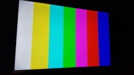
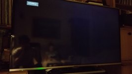
This Retrotink model that I am using is the basic one. With RGB input with SCART(Retrotink 2x SCART). It only has one button which is to activate the SCANLINES. But I have noticed that when upgrading to the latest version, when I press the button twice it shows me the screen cut into two halves. But the only thing I can see are the colored lines that the Retrotink shows without sending a signal to it. The moment I plug in the Neo Geo, everything goes dark.

Before sending RGB signal from the Neo Geo
20220602_013942.jpg
After
20220602_013925.jpg
 
Last edited:

Sho G.

Quiz Detective
10 Year Member
Joined
Apr 30, 2011
Posts
82
The problem is almost definitely the TV. The TV probably could be used with the MV-1C with a 1080p upscaler that can correct the sync, such as the Retrotink 5X or Framemeister.
Now that you mention it, I think mine is the 5x. Which would explain why component works perfectly through it into the new tv, but not into the component inputs of my old one.

My older tv has component, composite, hdmi, s-video, even a vga pc input that works great with Dreamcast. So I've got about a billion switch boxes and all the old consoles hooked up to it. But the new tv, nice as it is, is HDMI only. So I literally had to get the retrotink to get anything older than ps3 to work with it. I hate that, although I suppose it makes sense. Not many people nowadays want to hook up electronics that aren't at least HDMI.

So, yeah, Sho G. Either getting a higher end retrotink or using another tv is going to be your best bet in all likelihood.
The reason I bought the Retrotink 2x is because I wanted to connect the RGB outputs of the JAMMA connector directly to the Retrotink. At that time I think the Retrotink 5x was not yet sold. Anyway, could the RGB output of the JAMMA be connected directly to the Retrotink 5x?
 

Sho G.

Quiz Detective
10 Year Member
Joined
Apr 30, 2011
Posts
82
Do you know if the MVS works in general?

If so, whats the connection between the MVS and Retrothink?
MVS will output TTL levels for RGBS, you needs 75Ohm levels though, is there a THS RGB amp somewhere, or just resistors?
If it is neither, it's not supposed to work IMO.
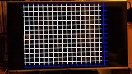
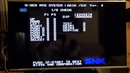
In general, the Neo Geo I think works well. I connected it directly to the SCART of the TV and it showed an image, although a little strange, since the upper and left part are cut off.

20220602_015330.jpg

There is nothing between the JAMMA connector and the Retrotink input. Should I insert 75 ohm resistors between the RGB signals and the Retrotink? The only thing I tried is inserting a 10k variable resistor between the Sync signal and the Retrotink. But there are no differences.
 
Last edited:

Sho G.

Quiz Detective
10 Year Member
Joined
Apr 30, 2011
Posts
82
I have the same Retrotink as you and can confirm 2 slot MVS compatibility is flawless. My super gun uses the Arcadeforge PCB with a SCART socket on it. Whatever they used for buffering resistors or whatever is exactly what is required.
Thanks for the info. I have seen how others have successfully connected the MV-1C with the Retrotink 2x SCART, but I don't know how they have connected it. Hopefully it's a resistor or connection thing.
 

Neo Alec

Ned's Ninja Academy Dropout
20 Year Member
Joined
Dec 7, 2000
Posts
11,994
Yes, that's wrong. You need to attenuate the RGB and sync signals. I assumed you were using a supergun that took care of that. You need at least 75 ohm resistors on the RGB lines and a 330 ohm resistor on the sync line, or you could damage the TV.
 

Sho G.

Quiz Detective
10 Year Member
Joined
Apr 30, 2011
Posts
82
Yes, that's wrong. You need to attenuate the RGB and sync signals. I assumed you were using a supergun that took care of that. You need at least 75 ohm resistors on the RGB lines and a 330 ohm resistor on the sync line, or you could damage the TV.
Thanks for the info. I thought the Retrotink was responsible for attenuating the signals. I'll try the resistors.
 

Neo Alec

Ned's Ninja Academy Dropout
20 Year Member
Joined
Dec 7, 2000
Posts
11,994
Nope. The tink is designed for consumer level signals.
 

Neo Alec

Ned's Ninja Academy Dropout
20 Year Member
Joined
Dec 7, 2000
Posts
11,994
Also, put 220uf caps on all 4 lines after the resistors.
 

Sho G.

Quiz Detective
10 Year Member
Joined
Apr 30, 2011
Posts
82
Another question I had is that looking at the Retrotink input lines, I only find RGB, Sync and Audo Left and Right. But I can't find the Video Ground signal. So I assumed that the video ground is taken from the same power supply. Is this possible?
 

Neo Alec

Ned's Ninja Academy Dropout
20 Year Member
Joined
Dec 7, 2000
Posts
11,994
It probably uses one ground connection for everything. Don't you have a scart cable that is already handling this?

If I were you I'd get a Neo Geo scart cable, and wire the MV-1C to a DIN jack with the resistors and caps.
 

Sho G.

Quiz Detective
10 Year Member
Joined
Apr 30, 2011
Posts
82
It probably uses one ground connection for everything. Don't you have a scart cable that is already handling this?

If I were you I'd get a Neo Geo scart cable, and wire the MV-1C to a DIN jack with the resistors and caps.
Thanks for the suggestion. Now I don't have a Neo Geo cable. I'm going to try to insert the resistors and capacitors. Are the capacitors electrolytic? In that case, would the JAMMA output be connected to the positive pin of the capacitor and the negative to the resistor, and from there to the Retrotink?
 

maki

Edo Express Delivery Guy
Joined
Jan 1, 2022
Posts
334
In general, the Neo Geo I think works well. I connected it directly to the SCART of the TV and it showed an image, although a little strange, since the upper and left part are cut off.

View attachment 57871

There is nothing between the JAMMA connector and the Retrotink input. Should I insert 75 ohm resistors between the RGB signals and the Retrotink? The only thing I tried is inserting a 10k variable resistor between the Sync signal and the Retrotink. But there are no differences.
as Neo Alec said, attenuate your RGBS levels, that should fix your Retrotink issues

on a side note, your pic shows the grid off center to the left on the horizontal, so CSYNC is front running the RGB signals
if you just use a electrolytic cap on the sync signal and not the RGB signals, it will delay the sync signal and thus "move the picture to the right"
 

Sho G.

Quiz Detective
10 Year Member
Joined
Apr 30, 2011
Posts
82
as Neo Alec said, attenuate your RGBS levels, that should fix your Retrotink issues

on a side note, your pic shows the grid off center to the left on the horizontal, so CSYNC is front running the RGB signals
if you just use a electrolytic cap on the sync signal and not the RGB signals, it will delay the sync signal and thus "move the picture to the right"
Thanks for the info. Very interesting. I'm going to attenuate the signals and try the electrolytic capacitor to center the image.
 

Sho G.

Quiz Detective
10 Year Member
Joined
Apr 30, 2011
Posts
82
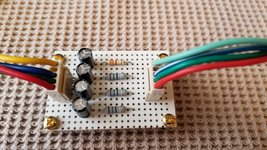
I have built the circuit with the 220uf capacitors and the 75 ohm resistors and the result is the same in all the tests I have done. I post a photo of the circuit in case I had made a bad connection. The JAMMA output enters through the positive of the capacitors and from the resistors it goes to the Retrotink. The image becomes dark in the same way as without the resistors. It's very strange. Something weird is going on with this Neo Geo or this Retrotink. On the other hand when I connect the Neo Geo to the RGB input of the SCART I still get a cropped image on the top and left side. Is it possible that something is damaged in the Neo Geo Sync line?

20220608_195212.jpg

Cropped Image Without Retrotink

20220609_003220.jpg
 
Last edited:
Top