Lemony Vengeance
Mitt Romney's Hairdresser,
- Joined
- Jan 30, 2012
- Posts
- 4,204
I have finally finished my JAMMA SNES project and as promised, here’s the Tutorial!
Part of the reason I’m doing this is to show my appreciation to the community that taught me everything I know about modding hardware. When I first thought about doing this nearly a year ago, I was amazed at how much info there was for the JAMMA Genesis mod, but not about the SNES. I made it my mission to not only figure out how to do it, but to also share what I learned in an effort to make it less secret.
Many thanks go out to Broken, 68k, and many others that helped me with advice and Video AMP testing with this.
Without Further Ado… The tutorial!
Step one – PREPARATION
Things you’ll need
1) Two SNES pads – FIRST PARTY!! (serious, can’t stress this enough, primarily for continuity and ease of modding).
2) An SNES of your choosing (Which is best? We’ll cover that later)
3) A GAMEBIT (if you don’t have one, hit the ‘bay)
Ok so, you’re going to need an SNES First and foremost. There’s a lot of debate about which ones produce the best RGB (the 1Chip being the best one of the old model, and the SNES Mini being the best of the new style) so find out which one you have. To do so, follow the instructions here:
http://kyorune.com/modding/article.php?id=13
I personally have two SNES consoles so I used the previously mentioned GAMEBIT and opened them up:

This one had a HUGE audio unit in it.. I was concerned about the space I was going to be using so I was relieved when I popped my second one open:

This one had a ton of room for things that I wanted to add to it so I decided to go with this one. Will you want to? *shrug* It’s really up to you.
I took every extra shield and heatsink off the board and put them and the screws in a Ziplock bag. I’m glad I did because they remained in that bag for the 7 months it took for me to research this build :P While the board is out of the case, use this time to familiarize yourself with where the wiring points are, and how you’re going to run your wires. The underside of the console doesn’t have a TON of space so make sure you plan ahead. A Silver Sharpie may not hurt either for path marking.
One final thing before you begin, look at the console case itself and gauge where you want to put the JAMMA edge, the L/R audio out (if you choose), The Volume pot (if you decide to add amplified mono audio over the edge) and the Kick Harness. This is where I placed mine:

Creating these mods first will help you know where to run wires and how long they need to be. Once you have everything figured out (wire runs, external facing mods, etc), you can move on.
Step Two – MODDING THE MOTHERBOARD
Things you’ll need:
1) Desoldering pump
2) Soldering Iron
3) Wire (22-26 gauge stranded)
4) Solder
5) Wire snips/strippers
6) An RGB AMP
7) L/R RCA audio connectors (Female)
8) A Kick Harness port of your choosing (I Use CPS2 style Kick harness ports in my mods)
9) A JAMMA edge (I used the JB-2 edge adapter from JAMMABOARDS.com
10) Screws and nuts to hold the various components in place
11) PATIENCE
First thing’s first, let’s get this puppy wired up for power! Even though the voltage regulator inside the SNES can handle 12V, I pulled mine out and wired it up for 5v (what it regulates the voltage to) for two reasons:
1) That heatsink takes up so much SPAAAAAAACE
2) With the controllers wired up inside it, you’re not going to be able to play it with external controllers anyway.
Here’s the voltage regulator:

Use your desoldering pump (or hakko 808 if you have it :P) to liberate it from the board and Use a small wire to Jump the “I” and “O” points. This will allow the 5V power from the edge to flow through the board.
Next step is to wire the 5V Line from the edge. In order to allow the power switch to work with the board, you need to run power from where the “Wall Wart” (AC adapter) connects to the console. That can be done here:

Solder it to the contact in the red box. You can de-solder the connector or leave it in.. I left mine in. I don’t like gaping holes in the things I mod. As for Ground, you can pretty much grab it from anywhere. I grabbed mine from the middle pin where the Voltage regulator used to be. Ease of access and all.
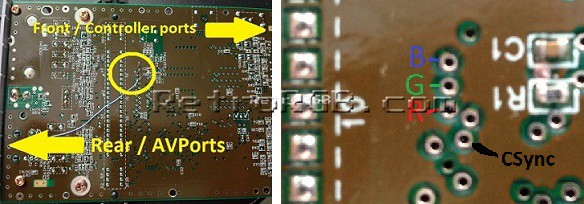
Once you have power, you can begin pulling Video/Sync/Audio from the rear AV connector.

Pretty straight forward. If you have an NTSC SNES, you’re in luck! NO LM1881N Sync Separation circuit needed! If this is you, pull C-Sync from pin 3 and wire that up to the JAMMA edge. If you don’t.. well. You’ll need to add one in. Grab C-video from pin 9 and wire it up to this circuit:
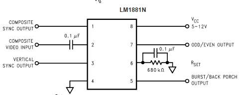
Grab C-sync out from pin 1 of that circuit and wire it up to the JAMMA edge.
Next is RGB! If you have an older SNES, you can grab it from the AV port! If you have an SNES Mini, you’ll need to grab it elsewhere:
DON’T WIRE IT UP TO THE EDGE! YOU WILL NEED AN AMP!
I was finally able to make mine work with one of Broken’s PCE RGB amps:
There is a 99% possibility that he will stop selling these very soon. When that happens, I will post the link to the schematics/gerber files for you to have some printed out for yourself.
This Amplifier works very well and is based around the THS7314 IC that every other Nintendo RGB mod uses. The colors seriously POP!
Take your RGB lines and wire them up to the amp, pull Ground and 5V from the JAMMA edge and wire them up to the amplifier circuit as well. Make sure that you place the amplifier in a place that won’t interfere with the top half of the console shell, or other components. I suggest mounting it with a piece of double-sided foam tape.
Now that video is out of the way, let’s tackle AUDIO!
Use the previously mentioned Diagram for audio pulls. I pulled ground for the RCA ports directly from the AV out since it was right there for me. If you choose to add in a mono audio amp and want both channels to run over the JAMMA edge, you’ll need to use this circuit to combine both channels:

This will make sure you don’t burn out the audio in the SNES. Combine those channels and wire it up to your volume pot, then your Amplifier, making sure to take placement into consideration.
Once that’s done, FIRE HER UP AND TEST HER OUT!!
Once you’ve confirmed that everything is working with Video/Audio, screw the motherboard back in to the bottom half of the console case.
PHEW! YOU’RE ALMOST THERE!
Step Three – CONTROLS!
Things you’ll need:
1) Two Genuine SNES controllers
2) Soldering Iron
3) Two SOP20 to DIP adapter boards (http://www.ebay.com/itm/2pcs-IC-SOP...445?pt=LH_DefaultDomain_0&hash=item417806bfad)
4) Desoldering Braid, A Desoldering pump OR A heat gun
5) Floppy/IDE Ribbon cable
Find two original SNES pads and pull the PCB out of them. The shells of the controllers can go in the garbage. This next part was a little tricky for me. I was originally going to cut the controllers down to conserve space inside the SNES and wire up some ribbon cable to the IC, but I read here http://forums.benheck.com/viewtopic.php?p=230707#p230707 that only the IC from the controller PCB is needed! I ordered some SOP20 to DIP boards and attempted to pull the V520B ICs off the boards while I waited… Man, these suckers were on there, TIGHT! I attempted to use Desoldering Braid to suck the solder up.. no go. Tried my MASSSIVE desoldering pump.. nothing. I finally cut the traces just below where the legs to the IC met the PCB with an Xacto knife and wedged it under there until the IC popped off pulling the traces with it. I know, brute force, but it did the job. If I was going to do it again, I’d use a heat gun and slide the IC off.
If you pulled the traces off as well, use your soldering Iron and make sure the pins don’t have any remnants of them and solder them to the SOP adapter board. Make sure you don’t bridge the pins! A little bit of solder goes a long way with these SMD ICs so don’t overdo it.
Once that’s done, review this diagram:

This is the pin out for the controls. With this in mind, cut some ribbon cable (or wire of your choosing) to the desired length, keeping in mind placement in the console. I used double sided foam tape on these boards and taped them under the JAMMA edge. Very little space used indeed! Once the wire is cut, Tin the ends and feed them through the through-holes. I re-used a section of the cables from the controllers for this:

Connect the wires from the adapter board to your JAMMA Edge and Kick Harness port in a configuration that works for you. Most games will allow for buttons to be re-configured, but choose a layout that you like. I personally went with the layout the Street Fighter games use. Once they’re wired up, secure them in place (again, Double-sided foam tape):

All that’s left to do is wire them up to the controller ports! There’s two ways to do this: The easy and most obvious way or the difficult but super incognito way:

I personally wired mine to the back of the controller ports. Super simple to access and fix if anything goes wrong or a wire comes loose. If you used the original wires, that is a very VERY strong possibility. The wires in them aren’t the greatest.
The other way is to wire them up to the bottom of the board. This requires that you take the motherboard out AGAIN and wire it up, then put it back in and make sure no wires wandered away from the tracks you set up.. it’s a pain. Make it easy on yourself and wire it up to the back of the controller ports:

Step Four – THE FINAL TEST!
Take your SNES to your cabinet, connect the JAMMA harness, the kick harness and Stereo audio (if you have a stereo amp) and fire it up. Choose a game, put it in the console and turn it on. You should now have controls, audio and VIDEO! YAY YOU!
Button her back up and enjoy your new JAMMA SNES!
Part of the reason I’m doing this is to show my appreciation to the community that taught me everything I know about modding hardware. When I first thought about doing this nearly a year ago, I was amazed at how much info there was for the JAMMA Genesis mod, but not about the SNES. I made it my mission to not only figure out how to do it, but to also share what I learned in an effort to make it less secret.
Many thanks go out to Broken, 68k, and many others that helped me with advice and Video AMP testing with this.
Without Further Ado… The tutorial!
Step one – PREPARATION
Things you’ll need
1) Two SNES pads – FIRST PARTY!! (serious, can’t stress this enough, primarily for continuity and ease of modding).
2) An SNES of your choosing (Which is best? We’ll cover that later)
3) A GAMEBIT (if you don’t have one, hit the ‘bay)
Ok so, you’re going to need an SNES First and foremost. There’s a lot of debate about which ones produce the best RGB (the 1Chip being the best one of the old model, and the SNES Mini being the best of the new style) so find out which one you have. To do so, follow the instructions here:
http://kyorune.com/modding/article.php?id=13
I personally have two SNES consoles so I used the previously mentioned GAMEBIT and opened them up:
This one had a HUGE audio unit in it.. I was concerned about the space I was going to be using so I was relieved when I popped my second one open:
This one had a ton of room for things that I wanted to add to it so I decided to go with this one. Will you want to? *shrug* It’s really up to you.
I took every extra shield and heatsink off the board and put them and the screws in a Ziplock bag. I’m glad I did because they remained in that bag for the 7 months it took for me to research this build :P While the board is out of the case, use this time to familiarize yourself with where the wiring points are, and how you’re going to run your wires. The underside of the console doesn’t have a TON of space so make sure you plan ahead. A Silver Sharpie may not hurt either for path marking.
One final thing before you begin, look at the console case itself and gauge where you want to put the JAMMA edge, the L/R audio out (if you choose), The Volume pot (if you decide to add amplified mono audio over the edge) and the Kick Harness. This is where I placed mine:
Creating these mods first will help you know where to run wires and how long they need to be. Once you have everything figured out (wire runs, external facing mods, etc), you can move on.
Step Two – MODDING THE MOTHERBOARD
Things you’ll need:
1) Desoldering pump
2) Soldering Iron
3) Wire (22-26 gauge stranded)
4) Solder
5) Wire snips/strippers
6) An RGB AMP
7) L/R RCA audio connectors (Female)
8) A Kick Harness port of your choosing (I Use CPS2 style Kick harness ports in my mods)
9) A JAMMA edge (I used the JB-2 edge adapter from JAMMABOARDS.com
10) Screws and nuts to hold the various components in place
11) PATIENCE
First thing’s first, let’s get this puppy wired up for power! Even though the voltage regulator inside the SNES can handle 12V, I pulled mine out and wired it up for 5v (what it regulates the voltage to) for two reasons:
1) That heatsink takes up so much SPAAAAAAACE
2) With the controllers wired up inside it, you’re not going to be able to play it with external controllers anyway.
Here’s the voltage regulator:
Use your desoldering pump (or hakko 808 if you have it :P) to liberate it from the board and Use a small wire to Jump the “I” and “O” points. This will allow the 5V power from the edge to flow through the board.
Next step is to wire the 5V Line from the edge. In order to allow the power switch to work with the board, you need to run power from where the “Wall Wart” (AC adapter) connects to the console. That can be done here:
Solder it to the contact in the red box. You can de-solder the connector or leave it in.. I left mine in. I don’t like gaping holes in the things I mod.
As for Ground, you can pretty much grab it from anywhere. I grabbed mine from the middle pin where the Voltage regulator used to be. Ease of access and all. Once you have power, you can begin pulling Video/Sync/Audio from the rear AV connector.
Pretty straight forward. If you have an NTSC SNES, you’re in luck! NO LM1881N Sync Separation circuit needed! If this is you, pull C-Sync from pin 3 and wire that up to the JAMMA edge. If you don’t.. well. You’ll need to add one in. Grab C-video from pin 9 and wire it up to this circuit:
Grab C-sync out from pin 1 of that circuit and wire it up to the JAMMA edge.
Next is RGB! If you have an older SNES, you can grab it from the AV port! If you have an SNES Mini, you’ll need to grab it elsewhere:
DON’T WIRE IT UP TO THE EDGE! YOU WILL NEED AN AMP!
I was finally able to make mine work with one of Broken’s PCE RGB amps:
There is a 99% possibility that he will stop selling these very soon. When that happens, I will post the link to the schematics/gerber files for you to have some printed out for yourself.
This Amplifier works very well and is based around the THS7314 IC that every other Nintendo RGB mod uses. The colors seriously POP!
Take your RGB lines and wire them up to the amp, pull Ground and 5V from the JAMMA edge and wire them up to the amplifier circuit as well. Make sure that you place the amplifier in a place that won’t interfere with the top half of the console shell, or other components. I suggest mounting it with a piece of double-sided foam tape.
Now that video is out of the way, let’s tackle AUDIO!
Use the previously mentioned Diagram for audio pulls. I pulled ground for the RCA ports directly from the AV out since it was right there for me. If you choose to add in a mono audio amp and want both channels to run over the JAMMA edge, you’ll need to use this circuit to combine both channels:
This will make sure you don’t burn out the audio in the SNES. Combine those channels and wire it up to your volume pot, then your Amplifier, making sure to take placement into consideration.
Once that’s done, FIRE HER UP AND TEST HER OUT!!
Once you’ve confirmed that everything is working with Video/Audio, screw the motherboard back in to the bottom half of the console case.
PHEW! YOU’RE ALMOST THERE!
Step Three – CONTROLS!
Things you’ll need:
1) Two Genuine SNES controllers
2) Soldering Iron
3) Two SOP20 to DIP adapter boards (http://www.ebay.com/itm/2pcs-IC-SOP...445?pt=LH_DefaultDomain_0&hash=item417806bfad)
4) Desoldering Braid, A Desoldering pump OR A heat gun
5) Floppy/IDE Ribbon cable
Find two original SNES pads and pull the PCB out of them. The shells of the controllers can go in the garbage. This next part was a little tricky for me. I was originally going to cut the controllers down to conserve space inside the SNES and wire up some ribbon cable to the IC, but I read here http://forums.benheck.com/viewtopic.php?p=230707#p230707 that only the IC from the controller PCB is needed! I ordered some SOP20 to DIP boards and attempted to pull the V520B ICs off the boards while I waited… Man, these suckers were on there, TIGHT! I attempted to use Desoldering Braid to suck the solder up.. no go. Tried my MASSSIVE desoldering pump.. nothing. I finally cut the traces just below where the legs to the IC met the PCB with an Xacto knife and wedged it under there until the IC popped off pulling the traces with it. I know, brute force, but it did the job. If I was going to do it again, I’d use a heat gun and slide the IC off.
If you pulled the traces off as well, use your soldering Iron and make sure the pins don’t have any remnants of them and solder them to the SOP adapter board. Make sure you don’t bridge the pins! A little bit of solder goes a long way with these SMD ICs so don’t overdo it.
Once that’s done, review this diagram:
This is the pin out for the controls. With this in mind, cut some ribbon cable (or wire of your choosing) to the desired length, keeping in mind placement in the console. I used double sided foam tape on these boards and taped them under the JAMMA edge. Very little space used indeed! Once the wire is cut, Tin the ends and feed them through the through-holes. I re-used a section of the cables from the controllers for this:
Connect the wires from the adapter board to your JAMMA Edge and Kick Harness port in a configuration that works for you. Most games will allow for buttons to be re-configured, but choose a layout that you like. I personally went with the layout the Street Fighter games use. Once they’re wired up, secure them in place (again, Double-sided foam tape):
All that’s left to do is wire them up to the controller ports! There’s two ways to do this: The easy and most obvious way or the difficult but super incognito way:
I personally wired mine to the back of the controller ports. Super simple to access and fix if anything goes wrong or a wire comes loose. If you used the original wires, that is a very VERY strong possibility. The wires in them aren’t the greatest.
The other way is to wire them up to the bottom of the board. This requires that you take the motherboard out AGAIN and wire it up, then put it back in and make sure no wires wandered away from the tracks you set up.. it’s a pain. Make it easy on yourself and wire it up to the back of the controller ports:
Step Four – THE FINAL TEST!
Take your SNES to your cabinet, connect the JAMMA harness, the kick harness and Stereo audio (if you have a stereo amp) and fire it up. Choose a game, put it in the console and turn it on. You should now have controls, audio and VIDEO! YAY YOU!
Button her back up and enjoy your new JAMMA SNES!
Last edited:
")
 hawt stuff Lem
