Jamma Genesis

MuppeT

War Room Troll
Joined
Jan 12, 2015
Posts
1,548
Heres where I think you can pull the colors and sync

2015-02-17_0918.png


The colors I'm pretty sure about, but the Sync may need to be traced back behind that cap. Give it a shot and let me know :)


Thanks for taking your time to help me! I will sure let you know once I give it a shot.
 

kraquepype

Armored Scrum Object
Joined
Mar 12, 2009
Posts
256
I like seeing bare PCBs but is there an advantage to connecting the fingerboard directly, vs wiring everything up and retaining the case? I'm thinking for a hostile arcade environment it'd make things more stable but what besides that?
 

bustedstr8

Trollbox Trade Federation,
Joined
Oct 15, 2007
Posts
943
If you want a solid mechanical connection to the pcb and to still use the original case, the JB-1 fingerboard fits perfectly into a Model 1 or 2 Genesis.

Spoiler:

15645371571_0193cbd118_b.jpg

15462488290_ce947ed260_b.jpg


Mendel

Vanessa's Drinking Buddy
Joined
Sep 3, 2012
Posts
1,187
Just a general tip to all the idiots like me out there with jamma genesis.

if you seem to have too low contrast/brightness on jamma genesis compared to actual arcade pcbs, check your voltage levels with a voltimeter.

if you dont have a proper voltimeter, francob makes excellent jamma voltimeters.

Basically, voltage levels on jamma seems to have a drastic impact on color brightness and contrast of my jamma genesis on new astro city. I was running the psu on too low voltage and I had to adjust the colors and brightness every time I plugged in the genesis and when I changed back to arcade pcbs. I have now adjusted the voltage and now it seems like the genesis runs fine with the same adjustments as my 4-slot for example. much more convenient. (I was running at 4.73, adjusted to 5.07 and things look up now)
 

MuppeT

War Room Troll
Joined
Jan 12, 2015
Posts
1,548
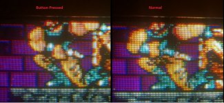
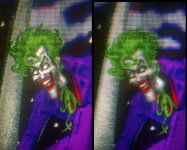
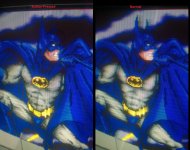
OK finally managed to do some work on the genesis. Connected everything but I am experiencing some oddities.
When I press certain buttons (Up/Down, Attack) the graphics get better in terms of details and contrast..
I suppose the graphics should be primary the way they are when it glitches as then the screen is a bit sharper, brighter and more details can be seen.

here are some pictures.

strange.jpgWP_20150327_010.jpgWP_20150327_013.jpg
 
Last edited:

skratch

n00b
Joined
Mar 25, 2013
Posts
1
Hi im attempting this mod and im having issues. When testing the video the sega logo pops up and looks fine, then for instance I have sonic two in I can barely see the title screen and when I start the game I see the first level for a second then it gets so dark I can barely see anything. Can anyone help?
 

Lemony Vengeance

Mitt Romney's Hairdresser,
Joined
Jan 30, 2012
Posts
4,204
Hi im attempting this mod and im having issues. When testing the video the sega logo pops up and looks fine, then for instance I have sonic two in I can barely see the title screen and when I start the game I see the first level for a second then it gets so dark I can barely see anything. Can anyone help?

Which model and revision?
 

Hrvat9

n00b
Joined
Sep 23, 2016
Posts
7
Necro bump, my sound is super low on my genny 2 with the KA2195D chip in my new Astro city.
Anyone have a pic of exactly where they too the sound from?
 

Shuri

Kula's Candy
10 Year Member
Joined
Jul 2, 2012
Posts
294
Super necro bumb.

Was looking at this project, seems fun I have a lot of sega genesis model2 so i want to try this.

Just a small question - I also found this tutorial: http://zorglub29.free.fr/repairlogs/md2jamma/ and for the controller part, they simply removed the genesis' control ports and soldered straight from the connection holes to to jamma fingerboard.

NOW! I see you guys are hacking up controller pads. Is there a particular reason for that? Is this for compatibility for 6 buttons game?
 

egg_sanwich

Windjammers Wonder
10 Year Member
Joined
Oct 9, 2012
Posts
1,379
Super necro bumb.

Was looking at this project, seems fun I have a lot of sega genesis model2 so i want to try this.

Just a small question - I also found this tutorial: http://zorglub29.free.fr/repairlogs/md2jamma/ and for the controller part, they simply removed the genesis' control ports and soldered straight from the connection holes to to jamma fingerboard.

NOW! I see you guys are hacking up controller pads. Is there a particular reason for that? Is this for compatibility for 6 buttons game?
If you look closely at the picture in your link, you can see the controller PCB beneath the console PCB. They have desoldered the controller ports but still gone through the original controller PCB.

This archive of the original tutorial linked from your post explains why directly wiring (without the controller pcb) is not possible:
 

SpamYouToDeath

I asked for a, Custom Rank and, Learned My Lesson.
15 Year Member
Joined
Oct 3, 2005
Posts
6,059
You could probably simulate a Genesis/MD 6-button pad with a simple microcontroller, rather than trashing a real pad.
 

mesmer

Crossed Swords Squire
10 Year Member
Joined
Jun 28, 2010
Posts
193
I think 6 button controllers use dark voodoo, but the 3 button ones are simple, no microcontroller needed.
 

SpamYouToDeath

I asked for a, Custom Rank and, Learned My Lesson.
15 Year Member
Joined
Oct 3, 2005
Posts
6,059
I think 6 button controllers use dark voodoo, but the 3 button ones are simple, no microcontroller needed.
Yeah, the 3-button pads just use a multiplex. If I recall, the 6-button controllers wait for you to toggle the mux 3 times within one frame, and then send XYZM on the d-pad inputs. Nobody should be sacrificing gamepads to do this.
 

Shuri

Kula's Candy
10 Year Member
Joined
Jul 2, 2012
Posts
294
so I gave it a try this morning and I ran into some issues. I'm fairly novice when it comes to this kind of encoder stuff but I'm eager to learn!

I get no sync, or anything at all. Tested this on my old 'test bench' MAS supergun on composite and on my OSSC setup.

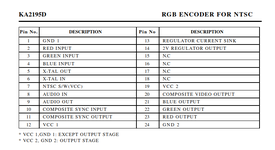
As it turns out, all 6 (!) of the sega genesis model 2 I have are are V1 with the Samsung KA2195D encoder, which seems to be pretty hated online. Looking at the data sheets I get this pinout

1629145370599.png

So I used the pins 21-22-23 for the RGB output, pin 1 for Ground, and pin 10 for Sync. The OP mentioned using Composite Sync Input on his sony encoder, so I went with the same strategy so that's why I went with pin 10.

Continuity is fine and coherent with my jamma finger board, everything points to where it should be.

I assume i'm just doing something wrong with the pins I use. I've just noticed the "VCC 2, GND2: Output Stage" part. Does it means that I should be using GND2, pin 24 for ground? I mean, since I'm using the output r-g-b pins?

The other mistake I can possibly be doing is with the Composite Sync pins. Maybe i'm suposed to be using the output sync pin?
 
Last edited:

egg_sanwich

Windjammers Wonder
10 Year Member
Joined
Oct 9, 2012
Posts
1,379
so I gave it a try this morning and I ran into some issues. I'm fairly novice when it comes to this kind of encoder stuff but I'm eager to learn!

I get no sync, or anything at all. Tested this on my old 'test bench' MAS supergun on composite and on my OSSC setup.

As it turns out, all 6 (!) of the sega genesis model 2 I have are are V1 with the Samsung KA2195D encoder, which seems to be pretty hated online. Looking at the data sheets I get this pinout

View attachment 51897

So I used the pins 21-22-23 for the RGB output, pin 1 for Ground, and pin 10 for Sync. The OP mentioned using Composite Sync Input on his sony encoder, so I went with the same strategy so that's why I went with pin 10.

Continuity is fine and coherent with my jamma finger board, everything points to where it should be.

I assume i'm just doing something wrong with the pins I use. I've just noticed the "VCC 2, GND2: Output Stage" part. Does it means that I should be using GND2, pin 24 for ground? I mean, since I'm using the output r-g-b pins?

The other mistake I can possibly be doing is with the Composite Sync pins. Maybe i'm suposed to be using the output sync pin?
I have the same encoder and was able to get it to work following ops guide.

I used pin 1 for ground, 10 for sync, 21/22/23 for RGB

double check you are tapping the right pins. Your pinout is confusing in that it doesn’t represent the actual layout of the chip. 1is across from 24, not 13 as shown in your pinout. 12 is across from 13.
 

Shuri

Kula's Candy
10 Year Member
Joined
Jul 2, 2012
Posts
294
I have the same encoder and was able to get it to work following ops guide.

I used pin 1 for ground, 10 for sync, 21/22/23 for RGB

double check you are tapping the right pins. Your pinout is confusing in that it doesn’t represent the actual layout of the chip. 1is across from 24, not 13 as shown in your pinout. 12 is across from 13.
That was EXACTLY the issue. It's working right now. I figured out a few minutes ago. I re-soldered everything and it works!
 

Neodogg

Dogg-Father,
20 Year Member
Joined
Nov 27, 2002
Posts
5,607
I know I not the smartest but don’t you need to use pin 11 for sync out?
 
Top