MV1F Battery Leak - No sound

Joined
Oct 4, 2001
Posts
302
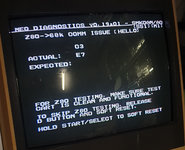
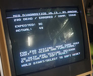
I pulled my MV1F out of storage yesterday and was disappointed to find it worked fine but had no sound. The Unibios can't even start the Jukebox, which seems like it's possibly a Big Clue but I don't know what it suggests. Seems like the whole sound subsystem is offline? IDK.

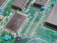
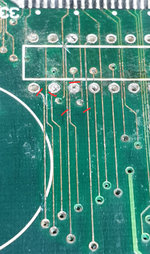
The damage to the board seems minimal. Some peeling and some scruffy looking traces, but after giving it a scrub and a bath it seems to be fine. I toned out every trace with a multimeter and they all seem to be fine (based on the 40 or so circuits I checked). No shorts, no cuts. That glued-on petrified foam cover on the base is still very much affixed, so I could not check the base of the PCB.

I did a search but couldn't find anything that matched this issue specifically, so my apologies for asking again what is certainly a common question, but:

tl;dr - battery damage, no sound, no jukebox. What does that suggest is the problem?

Thanks for any clues or tips.

NeoGeo-BatteryDamage.jpg
 
Last edited:

BIG BEAR

SHOCKbox Developer,
20 Year Member
Joined
Dec 14, 2001
Posts
8,237
You need to remove that battery ASAP..acid is all over the place.and the problem is your 6116 where it's corroded from the acid.there could also be some broken tracks in that area..
You will need to clean that whole area with some 90% isopropyl alcohol.
Edit: I just read your whole post...remove that battery and replace that 6116
BB
 
Joined
Oct 4, 2001
Posts
302
Oh gosh yeah, that battery was out 10 seconds after I took the picture. I scrubbed the whole area out with some water and baking soda and a toothbrush.

Time to find a 6116 chip! Pretty sure I don't have any in the parts bin.

Thanks for the tip, I'll report back with my progress.
 
Joined
Oct 4, 2001
Posts
302
Progress update: seems like everyone selling these chips is in China. It's not my first choice for picking one up.

Aaaand then I remembered I've got like six AES systems kicking around that have like 5 compatible chips each. Time to break out the de-solder. ^__^
 

BIG BEAR

SHOCKbox Developer,
20 Year Member
Joined
Dec 14, 2001
Posts
8,237
Progress update: seems like everyone selling these chips is in China. It's not my first choice for picking one up.

Aaaand then I remembered I've got like six AES systems kicking around that have like 5 compatible chips each. Time to break out the de-solder. ^__^
Don't forget to add a socket if you have them.
BB
 

Neo Alec

Ned's Ninja Academy Dropout
20 Year Member
Joined
Dec 7, 2000
Posts
11,994
Not what I'd call minimal. Looks like pretty significant leakage. A cautionary tale for removing the batteries. Good luck with it -- hope it's only a broken trace or two.
 
Joined
Oct 4, 2001
Posts
302
Not what I'd call minimal. Looks like pretty significant leakage. A cautionary tale for removing the batteries. Good luck with it -- hope it's only a broken trace or two.
The leakage area was significant, for sure. The damage seems limited. I haven't found any traces that have been severed, and I've checked pretty much everything within the leakage area. Every nearby component and via is still connected to some other place on the board.

Maybe I got lucky, or maybe I'm overlooking something, I wouldn't dare bet either way. =)
 

maki

Edo Express Delivery Guy
Joined
Jan 1, 2022
Posts
334
I have to agree that is not "minimal" damage, quite the contrary.
You still haven't found the cause of the missing sound, a bit early to talk about luck here IMO.
Some traces are running below ICs and are hard to spot if they are interrupted.

You should really the the foam off the bottom of the PCB, chances are it soaked up acid as well.
Soak the foam in IPA or glue remover to get it off.
 
Joined
Oct 4, 2001
Posts
302
Well typically when I see battery damage, there's lots of actual damage. Traces just etched away, gobs of acid lichen everywhere. This may be 'bad' it's probably the least worst one I've ever had to deal with. ¯\_(ツ)_/¯
 
Joined
Oct 4, 2001
Posts
302
Progress report:

Very little progress to report. I managed to get the chip out of the home system, but the MVS unit is putting up a mighty resistance. I can't use a solder sucker or braid to do the job, so I bought a hot air station and that doesn't work either.

I'd love some tips for getting that sucker out of there. I mean, I could just cut it, but... Rather do it right, if I can.
 

BIG BEAR

SHOCKbox Developer,
20 Year Member
Joined
Dec 14, 2001
Posts
8,237
The tools you have should work so if you can cut it out safely,do it.The chip is bad anyway...
BTW,sometime you have to apply solder to what already exists to get things loosened up,sometime a generous amount.
BB

Progress report:

Very little progress to report. I managed to get the chip out of the home system, but the MVS unit is putting up a mighty resistance. I can't use a solder sucker or braid to do the job, so I bought a hot air station and that doesn't work either.

I'd love some tips for getting that sucker out of there. I mean, I could just cut it, but... Rather do it right, if I can.
 

Neo Alec

Ned's Ninja Academy Dropout
20 Year Member
Joined
Dec 7, 2000
Posts
11,994
Progress report:

Very little progress to report. I managed to get the chip out of the home system, but the MVS unit is putting up a mighty resistance. I can't use a solder sucker or braid to do the job, so I bought a hot air station and that doesn't work either.

I'd love some tips for getting that sucker out of there. I mean, I could just cut it, but... Rather do it right, if I can.
Add some flux and solder. If you're still really stuck you could try some chip quik, but that's really meant for surface mount chips.
 

maki

Edo Express Delivery Guy
Joined
Jan 1, 2022
Posts
334
I managed to get the chip out of the home system, but the MVS unit is putting up a mighty resistance. I can't use a solder sucker or braid to do the job, so I bought a hot air station and that doesn't work either.
Since the battery acid leaked, there is now corrosion on the solder points, a "patina", that prevents proper heat transfer.
It is enough to physically scratch it away, go for "shiny metal", that will be easier to solder.
I use a dentists pick for that, people will recommend glass pens, I advice against them because of the really nasty dust they'll leave.
Then tons of flux and desolder braid.

I'd also recommend clipping the legs of the IC to remove it, then desolder each leg individually, that way you can preserve the PCB/traces as much as possible.

Edit:
Did you already use white vinegar to neutralise the acid that soaked into the PCB?
Otherwise the acid will keep doing its jobs over the next years/decades
 
Joined
Oct 4, 2001
Posts
302
Thanks for the advice, everyone. I did know enough to add a lot of fresh solder and flux. It turns out my problem was following internet advice, and running 350C with the hot air. Cranking it up to 370C (and running the soldering iron at 450 (!!!)) made it much more effective, and I got the chip out with relative ease. It's not beautiful work, I'm not proud. But it seems like I didn't do any more damage. 🤞

Now I'm waiting for my socket to arrive. Thankfully only a week lead time, not 12 months like too many other things these days.

In the meantime I'm testing out the traces. So far so good.
Did you already use white vinegar to neutralise the acid that soaked into the PCB?
I used baking soda but yes, it was the first thing I did after clipping the battery out.
 

Attachments

  • NeoGeo-BatteryDamage-2.jpg
    NeoGeo-BatteryDamage-2.jpg
    716.5 KB · Views: 6
  • NeoGeo-BatteryDamage-3.jpg
    NeoGeo-BatteryDamage-3.jpg
    685.3 KB · Views: 6

maki

Edo Express Delivery Guy
Joined
Jan 1, 2022
Posts
334
IMO get the foam off or safe yourself the effort to bother to fix this, the foam is full of acid, nothing you fix makes sense while the foam is still there

the usual order is vinegar, then baking soda
 
Joined
Oct 4, 2001
Posts
302
IMO get the foam off or safe yourself the effort to bother to fix this, the foam is full of acid, nothing you fix makes sense while the foam is still there
Yup, my isopropyl alcohol is en route with the chip socket. Might as well do what I can while I wait, right? So far though there's zero sign of any acid on the bottom side. I'll know for sure soon enough.
 
Joined
Oct 4, 2001
Posts
302
While I wait for my parts to arrive I started doing some cleanup and checked out all the traces. While I thought these checked out fine when I tested them before pulling out the 6116, they're very much dead now. These are the traces closest to the battery, so it makes sense that they were, if not already dead or intermittent before, the first to die when I put the heat on 'em for an hour.

I checked every other via on both sides and they all check out fine. Gonna have to put some effort into these five.

The red marks indicate the precise location of the break.
 

Attachments

  • NeoGeo_Repair-4.jpg
    NeoGeo_Repair-4.jpg
    691 KB · Views: 4
Joined
Oct 4, 2001
Posts
302
OK, the socket arrived, the alcohol arrived, I got that wretched foam panel off, and cleaned the bottom side of the PCB. I put the socket in, with nice little wires connecting the broken traces, and hey, I have sound!

It's not 100% correct. Pulstar makes a lot of wrong sounds, and SamSho 3 is almost entirely silent, except for some wrong sounding grunts during a match.

So I think I'm going to have to trace a lot more stuff and look for problems.
 
Joined
Oct 4, 2001
Posts
302
Alright, this might be the final update: Whatever the problem is now, remains a mystery.

I've traced every single chip pin and via within a 5cm radius from the battery and they all seem to be fine. I've re-flowed all the SMD chips in that radius, to no avail.

Everything works but the sound. The sound works with some errors for Pulstar, but aside from the neo-geo boot jingle, it's almost entirely silent for SamSho 3. The unbios jukebox throws an error. It's baffling, and I suspect, beyond me at this point.

I'd love some more tips, but without any ideas I'm basically ready to write this one off. =(
 
Joined
Oct 4, 2001
Posts
302
Thanks to a clue from @Razoola I'm back at it. The jukebox error means that the 68k isn't getting a response from the Z80 through the shared port.

So I'm checking every single pin between the Z80, NEO-DO, 2610, 6216, etc.

Starting with the Z80, it checks out every pin to the NEO-DO and 6216 RAM. I've checked every data and address line in the sound system, from YM2610 to 6216 RAM to Z80 and the SM1 ROM, as well as the signals between the 68000 and the NEO-DO, and between NEO-DO and the 43256 RAMs.

So if it's not the circuit, it's the chips, I guess. =(
 

maki

Edo Express Delivery Guy
Joined
Jan 1, 2022
Posts
334
have you tried using the DIAG BIOS?

it would report this error directly:
The jukebox error means that the 68k isn't getting a response from the Z80 through the shared port.
and it can detect other problems

measuring continuity is really good, but also check the VCC on the ICs when its on

do you have a logic probe or an oscilloscope?

logic probes can be quite cheap, just make sure it can support the high frequencies of the NeoGeo, 24Mhz
 
Joined
Oct 4, 2001
Posts
302
I've never heard of the Diag BIOS, I'll look into it. Thanks for the tip.

I have a logic probe, but it's old and simple. So old and simple that it doesn't have a rated speed. ^__^;

EDIT: oof, I gotta put a socket into a cart for the Z80 tests? I've only got 2 carts and I'd hate to wreck either one. I guess it's just the first tests for now.
 
Last edited:
Joined
Oct 4, 2001
Posts
302
OK, so I managed to burn the diag BIOS and M1, socketed in my SamSho III cart.

Running the 68k diagnostic reports no errors. But the Z80 diagnostics won't run at all.

Z80 SLOT SWITCH IGNORED (SM1) SM1 OTHERWISE LOOKS UNRESPONSIVE

Pressing START at this point runs the diagnostic on the cartridge M1, which fails because the whole Z80 is reportedly unavailable.

Not wholly certain what to do next so I'd love some advice. I'll try and find my logic probe and see if I can work out whether the Z80 is active at all, but beyond that, replacing it is my only idea.
 

maki

Edo Express Delivery Guy
Joined
Jan 1, 2022
Posts
334
Joined
Oct 4, 2001
Posts
302
I did use the .19 version first, then .19a01. Both gave basically the same report: communication error, Z80<->68k.

Digging into it with the github error docs, I'm getting beep code 001100, which is
old diag: Z80<->68k COMM. ERROR (DATA)
new diag: 68k->Z80 COMM ISSUE (HANDSHAKE)

According to the new docs, the 68k is basically not getting any useful data from the Z80. It couldn't switch the ports (not necessary in a 1-slot, but still it tries) and forcing the z80 to run the code doesn't result in a useful response.

According to the old docs,

Z80 isn't receiving the expected data from the 68k communication I/O port. Most likely an issue with the Z80 data bus or control signal trace to the chips that control the port (NEO-C1, NEO-D0).
  • Z80 D0~D7 → NEO-C1 SD0~SD7
  • Z80 IORQ (20) → NEO-D0 IORQ (37)
  • NEO-D0 SDZ80R (41), SDZ80W (43) → NEO-C1 SDZ80R (84), SDZ80W (85)

Sooooo, the upshot I guess is I'll be checking the circuits indicated by the old docs, and hoping it's not another dead chip. I don't look forward to yanking that z80. Prolly just cut it out...
 

Attachments

  • MVS-diag-2.jpg
    MVS-diag-2.jpg
    1.6 MB · Views: 3
  • MVS-diag-1.jpg
    MVS-diag-1.jpg
    1.9 MB · Views: 3
Last edited:
Top