Consolized MV1C issue: need help

Fulkelmis

Kuroko's Training Dummy
Joined
Jul 8, 2012
Posts
71
Hi folks,
I am doing a 2nd consolised MV1C for a friend. I have checked the voltage after soldering, everything looks good. Followings are the connexions:
Ground: 1, 2, 27, 28, A, B, E
+5V: 3, 4, C, D
Green: N
Sync: P
Red: 12
Blue: 13
Sound: jamma nation stereo mod.

As a result, I have no image and no sound...

Note that:
- I used jamma nation tutorial and double (triple) checked (with a multimeter)... without finding the issue.
- video signals (except sync) are connected straight to a RGB to VGA connector.
- I have tested it with a MVS cart (which is working, tested on my other CMVS), and without.
- Before soldering the wires on the MOBO, I have tested it on my other CMVS installation, using a jamma adapter: it was working as well.

I don't want to unsolder my wires to test it back on my other installation, due to lack of time.

Does anyone have any clue to help me?
Thanks
 

aha2940

AH, A, COLUMBIAN!,
Joined
Dec 15, 2013
Posts
2,528
Hi

Maybe if you post pics of your work, some of the more technical guys here can help with the issue. On a side note, it's generally better not to solder directly on the pads of the board, using a jamma connector is preferred, because it simplifies attaching / detaching of the board if it gets bad and can also be used with other jamma-compatible boards.

Regards.
 

jesesfbi

Ninja Combat Warrior
Joined
Jan 23, 2012
Posts
525
Don't you have to connect sync? And I thought those rgb to vga needed a HV sync instead of normal sync.
 

Xian Xi

JammaNationX,
15 Year Member
Joined
Dec 1, 2005
Posts
27,750
What exactly is ground E?

If you don't have sync connected then that could be the problem. Some TVs will only produce sound if an image is present on the screen.
 

Atro

Who?,
20 Year Member
Joined
Jan 30, 2002
Posts
9,217
What exactly is ground E?

If you don't have sync connected then that could be the problem. Some TVs will only produce sound if an image is present on the screen.

Oh boy!

If he's referring to the Jamma connector Pinout, he's using it as -5V instead of ground.
 

Fulkelmis

Kuroko's Training Dummy
Joined
Jul 8, 2012
Posts
71
Hi,

yes I know but I can't. The enclosure is so small that I have to save space. I just checked by unsoldering everything and plugging it into my other CMVS with a jamma connector, it works. That means there is a trick with rgb connexions and lcd display.
Can I connect rgb signals up to lcd display without an adapter ? May be it expects a "command" signal like another +5V - mixing the video from the working CMVS and the sound from the new one seems working.

To Altro: nop, it is the letter for the pin below the MOBO.
To Xian Xi: my adapter is a "simple" cable from rgb to vga... without a sync. Where to plug it?

Here is the link of my cable:
http://static.gamespot.com/uploads/original/1536/15360549/2396463-9736588284-VGA_M.jpg
 
Last edited:

Xian Xi

JammaNationX,
15 Year Member
Joined
Dec 1, 2005
Posts
27,750
You need a VGA encoder. RGB can not be displayed on a VGA monitor unless the monitor will accept a 15khz RGBS signal. Most VGA monitors only accept 31khz via RGBHV.
 

Atro

Who?,
20 Year Member
Joined
Jan 30, 2002
Posts
9,217
To Altro: nop, it is the letter for the pin below the MOBO.

It's just "Atro" ...

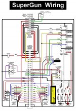
According to this schematic, the E letter, obviously stands for -5V and not ground.
I was assuming you were referring to the jamma pinout connector.

SuperGun.jpg

It seems you made a small rookie mistake by confusing us with the "e" with the "E".
Small "e" is a ground point yes, "E" is -5V.
 

mikejmoffitt

Mickey's Coach
Joined
Feb 6, 2014
Posts
578
Test audio without your TV involved. Headphones, an amplifier with line-in, or even hook a speaker up to the JAMMA mono speaker connection (if you haven't removed the amplifier from the PCB). Look for the sign of life.

For your RGB->VGA connection, be sure that 1) you have connected C-Sync to the HSYNC pin, as that's typically where that goes on a VGA connection. Also be sure your monitor / television will accept 15KHz horizontal sync (~240 lines) and is not VGA resolution only. Thirdly, ground VGA pins 5-10. Many monitors rely on checking some of those to be sure a cable is connected.
 

Fulkelmis

Kuroko's Training Dummy
Joined
Jul 8, 2012
Posts
71
Ok, I have tried something different; I have connected (with a 100 ohm resistor for each R/G/B/S/+5V):
- blue line (13) to scart pin 7
- red line (12) to scart pin 15
- green line (N) to scart pin 11
- sync line (P) to scart pin 20
- +5 line to scart pin 16
- video ground line to scart pin 5
Check with my lcd and a CRT, no signal on both. May be I need to ground more line on the scart connector?
 

Xian Xi

JammaNationX,
15 Year Member
Joined
Dec 1, 2005
Posts
27,750
Ok, I have tried something different; I have connected (with a 100 ohm resistor for each R/G/B/S/+5V):
- blue line (13) to scart pin 7
- red line (12) to scart pin 15
- green line (N) to scart pin 11
- sync line (P) to scart pin 20
- +5 line to scart pin 16
- video ground line to scart pin 5
Check with my lcd and a CRT, no signal on both. May be I need to ground more line on the scart connector?

Too much voltage to pin 16, put a 180-300ohm resistor inline with pin 16 and +5v. That will trigger the RGB mode correctly.
 

Fulkelmis

Kuroko's Training Dummy
Joined
Jul 8, 2012
Posts
71
Thx Xian. I tried, no more success. What is the expected value?
I have added a photo of my test scart, not the final job of course :-p
 

Attachments

  • photo-1.JPG
    photo-1.JPG
    720.7 KB · Views: 111

jesesfbi

Ninja Combat Warrior
Joined
Jan 23, 2012
Posts
525
Strange suggestion but try it. When I did my last cmvs I had to add a voltage divider circuit to the RGB lines to work with the encoder I had since the rgb voltage was too high and I has to step it down to lower than 1V levels.
 

Fulkelmis

Kuroko's Training Dummy
Joined
Jul 8, 2012
Posts
71
I tried voltage divider on +5V to get 0,83V on 16. Still not working. After checking the other voltage (R/G/B 2-300mV) I found that sync is quite high, around 2.5V. Is that correct?

Edit: when I connect scart 1 & 3 to audio, audio is working.
 
Last edited:

fremen

Hardened Shock Trooper
Joined
Aug 4, 2010
Posts
433
Hi,

One little thing, are you sure that your SCART TV entry is an RGB SCART entry?? Sometimes TV's have two SCART entries, one is RGB and the another not, if your TV only has one it is possible that not be RGB.

I see that you didn't put a resistor/pot in the Sync line, you need one, at least 2k2.

Saludos
 
Last edited:

Fulkelmis

Kuroko's Training Dummy
Joined
Jul 8, 2012
Posts
71
Thx. And how do you know if your tv is rgb capable? In the meantime, I have put a 100ohm resistor on it. I will try with more.
 

fremen

Hardened Shock Trooper
Joined
Aug 4, 2010
Posts
433
Hi,

Thx. And how do you know if your tv is rgb capable? In the meantime, I have put a 100ohm resistor on it. I will try with more.

Dou you have another console with SCART cable?? If yes, please could you measure the voltage at SCART pin 16?, if it is around 1volt and you can see the console in the TV then you have an RGB SCART.

Un saludo
 

Fulkelmis

Kuroko's Training Dummy
Joined
Jul 8, 2012
Posts
71
No I don't have.
My TVs:
- crappy CRT: SEG 3607 TX S
- Samsung LT19B300.
I have tested it with 1 and 1,3kohm on sync, not better (I have no more spare resistor).
Which voltage if should have on each scart pins?
 

jesesfbi

Ninja Combat Warrior
Joined
Jan 23, 2012
Posts
525
Okay what encoder are you trying to use? And putting resistors in series is not a voltage divider circuit lol.
 

Fulkelmis

Kuroko's Training Dummy
Joined
Jul 8, 2012
Posts
71
That's why I am asking about the voltage.... I have done a voltage divider for pin 16, but I am running out of resistor right now. And I need the expected voltage for each pin to order the good ones :-;
 

jesesfbi

Ninja Combat Warrior
Joined
Jan 23, 2012
Posts
525
That's why I am asking about the voltage.... I have done a voltage divider for pin 16, but I am running out of resistor right now. And I need the expected voltage for each pin to order the good ones :-;

We need to know which encoder you are using so we can help determine the input voltage for that encoder. Also like I said that wasn't a voltage divider circuit.
 

Vigormortis

Armored Scrum Object
Joined
May 30, 2013
Posts
268
He's not using an encoder. His first attempt was RGBS to VGA with a straight wire which was doomed from the start. His second attempt is RGBS to SCART, directly to the SCART inputs on his TVs.
 

Atro

Who?,
20 Year Member
Joined
Jan 30, 2002
Posts
9,217
His second attempt is RGBS to SCART, directly to the SCART inputs on his TVs.

This one's a no brainer.

It's pure RGB glory out of the MV1C directly to the scart pins
Something has to be incorrectly wired as scart output solves a lot of problems.
 
Top