Consolizing MVS, complete noob needing helps!

mannion

n00b
Joined
May 16, 2005
Posts
41
I am setting out consolizing this MVS I picked up because I just can't afford the games I want to play for my AES. I'd never part with my beloved AES but still.

I am in the UK and I need a little bit of help planning which mods to do and how to actually do them.

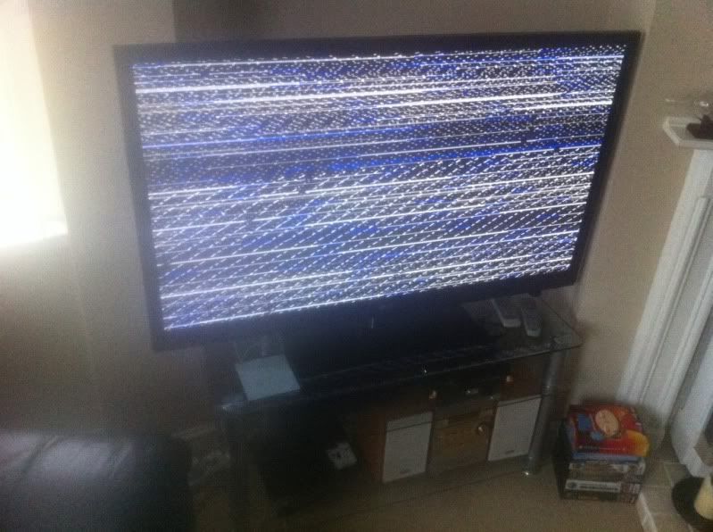
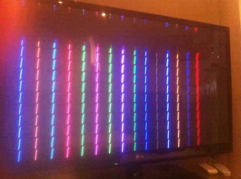
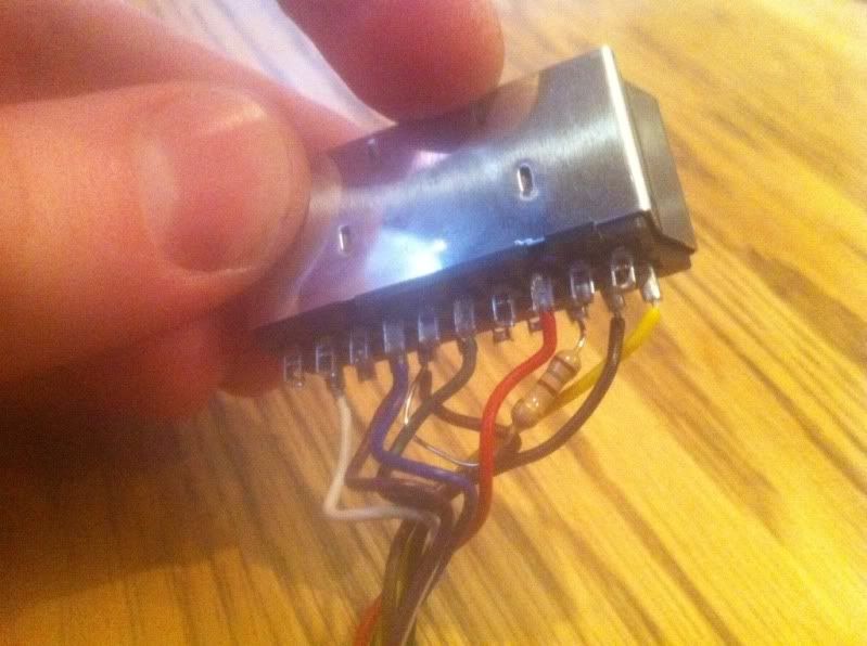
Basically I have an MV1fz motherboard which I got from eBay for £40. For a TV I have a 50" plasma which has every kind of connection, including scart. Given that I have scart available would scart be best to use, or component?

For a power supply I have found a 5V 3A plug I had spare so I will just get a socket for that to power it, I tried it on my AES and it powered it fine.

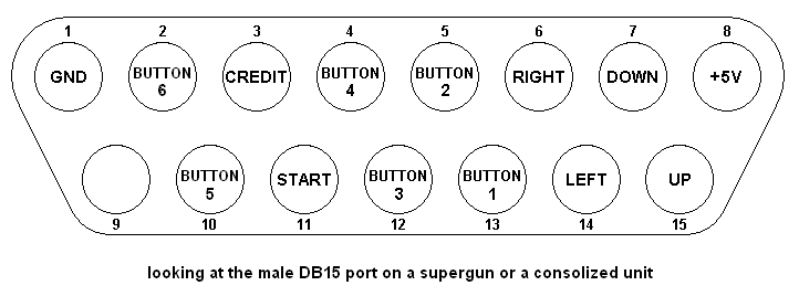
For joysticks I have 2 old style (big) AES sticks so I'll get female sockets for those to use.

I am going to try to make it look as nice as I can so I'm not going to use a Jamma harness as it's a bit messy.

Any input and guides will be GREATLY appreciated, I'll keep this thread as my little project thread showing my progress.

Cheers
 
Last edited:

alphagamer

Aero Fighters Flyboy
Joined
Jun 7, 2009
Posts
2,091
Scart is the best, because it is native RGB input, no signal conversion needed -> no quality loss.

5V 3A is fine for a one slot.

Pinouts:
jamma_pinout_engadget_howto.jpg


db15_laugh.PNG


200102_scart_2.gif


Good luck consolizing, I hope you have fun with this project.
 
Last edited:

mannion

n00b
Joined
May 16, 2005
Posts
41
Great thanks for the info I'll just go scart then.

I'll do the 5V only mod first then do the scart. I was wondering if instead of mounting a big scart socket on the motherboard I could use something more compact like a socket from a Playstation or something, can anyone recommend anything or should I just put a scart socket on?
 

Xian Xi

JammaNationX,
15 Year Member
Joined
Dec 1, 2005
Posts
27,750
You can always use a chassis mount 8 pin din socket just like on the Neo AES.
 

mannion

n00b
Joined
May 16, 2005
Posts
41
Don't know how I didn't think of that lol, I can order up an AES cable from ebay that way and make life easier.

This will do, right?

$(KGrHqMOKooE6eVU7UV4BOo-,(u0Vw~~60_35.JPG


It's from this auction, don;t think the picture is of an 8 pin socket but the auction is?

http://www.ebay.co.uk/itm/Panel-Mounting-Circular-Locking-DIN-Socket-8-Pin-AS309-/150681853272?pt=UK_BOI_Electrical_Components_Supplies_ET&hash=item2315569d58

Also can I buy a unibios from a member on here? (I'm in the UK)

Also just bought my first MVS cart, Metal Slug! Buzzing to get this done for that alone!!!
 
Last edited:

mmmonkey

Quiz Detective
Joined
Aug 6, 2008
Posts
83
Have fun :-) its great doing your first CMVS!

If you buy an AES RGB lead, it might be mono only, unless it also connects to the AES headphone socket - so you may need to rewire it anyway.

I usually buy matching plug and socket, then grab any old consoles stereo RGB lead and butcher it up (unless you have spare cable, scart plugs etc)

Lots of info on xian xi's site :-)

Pete
 

alphagamer

Aero Fighters Flyboy
Joined
Jun 7, 2009
Posts
2,091
I usually buy matching plug and socket, then grab any old consoles stereo RGB lead and butcher it up (unless you have spare cable, scart plugs etc)

This.

I bought a brand new Gamecube RGB Scart cable dirt cheap from Playasia and used that.
 

Xian Xi

JammaNationX,
15 Year Member
Joined
Dec 1, 2005
Posts
27,750
Have fun :-) its great doing your first CMVS!

If you buy an AES RGB lead, it might be mono only, unless it also connects to the AES headphone socket - so you may need to rewire it anyway.

I usually buy matching plug and socket, then grab any old consoles stereo RGB lead and butcher it up (unless you have spare cable, scart plugs etc)

Lots of info on xian xi's site :-)

Pete

The beauty of making your own CMVS is you can use a custom pinout on the 8 pin din socket. Just let the seller know what your pinout is and they should be able to help you or you can do it yourself.

Since you don't need both composite sync and composite video, use one of them for audio R. And just make sure the cable matches that as well.
 

mannion

n00b
Joined
May 16, 2005
Posts
41
So last night cleaned my motherboard up then I followed your fantastic guide for the 5V only modification, I think it went well.

I'm heading over to Maplins after work today to get the bits I need to be able to power the board up!
 

mannion

n00b
Joined
May 16, 2005
Posts
41
I'm a bit confused about powering the board, I have 5V only modded it, so am I right in thinking I just now supply 5V to 3,4,C,D and then ground 1,2,A,B and ignore everything -5v and 12v?

Also I am going to wire the 5V feed to the sticks/pads so which pin can I solder that onto?

Also finally, the diagram above of the 15 pin socket, is looking from the pin side (not solder side) of the male connector, right?
 

Xian Xi

JammaNationX,
15 Year Member
Joined
Dec 1, 2005
Posts
27,750
Correct, only need to wire up the +5v and ground. Usually for 1 slot boards you don't need to wire up all 4 +5v spots since the unit doesn't use much power. You can use just one and it will be fine.

As for the controller ports, yes that is the front side of the connector and +5v goes to pin 8.
 

mannion

n00b
Joined
May 16, 2005
Posts
41
Sweet man, thanks. I'll upload a few pictures tomorrow, quite pleased with how it's turning out for my first go.
 

mannion

n00b
Joined
May 16, 2005
Posts
41
Last night I finished all the wiring for power and tried it. The 5V LED illuminated at least so hopefully all is well with the mods I have done.

Does anyone have the pinout for the AES 8 pin connector, I may as well wire it the same as that I guess, but I'll add stereo sound so I don't have an ugly stereo jack going on.
 

mannion

n00b
Joined
May 16, 2005
Posts
41
It was all goin well until I tested it lol

bp8G


That said, as I don't have an MVs cart yet I font really know what the board should display when it is powered up? I just get that scrambling and a slight buzzing sound. Might need to try it on a CRT see if it's any different?

I don't have the composite sync connected, makes mo difference when I do connect it.

The cable o am using is RgB scary which works fine with my AES.

Stumped.
 

fremen

Hardened Shock Trooper
Joined
Aug 4, 2010
Posts
433
Hi,

You need to put a 100 Ohms resistor in the sync, pin 4 of the din (in the RGB cable) to pin 16 of the SCART (I usually put the resistor into the SCART).

Saludos
 

mannion

n00b
Joined
May 16, 2005
Posts
41
Hi thanks for the reply, So that's jamma pin P to din pin 4 them 100 ohm resistor them scart pin 16?
 

mannion

n00b
Joined
May 16, 2005
Posts
41
Here's what I had originally

a7096b64.jpg


Then i had this

73fd6cc9.jpg


The cable I'm using already has the resistor,

8adecfea.jpg


Pin 4 of my din is currently just 5v, should that be to sync? (pin P)
 

Xian Xi

JammaNationX,
15 Year Member
Joined
Dec 1, 2005
Posts
27,750
I dont know if I am just seeing things but it looks like RGB are on the wrong pins. Looks like they are on 17, 13, 9 instead of 15, 11, 7. I'd confirm the wiring on that cable.
 

mannion

n00b
Joined
May 16, 2005
Posts
41
Just checked it they are on 7, 11, 15 as they should be, this cable also works fine on my AES
 

Xian Xi

JammaNationX,
15 Year Member
Joined
Dec 1, 2005
Posts
27,750
Well that narrows it down to your wiring on your CMVS. What points did you tap RGB from and sync? Can you take a picture?
 

fremen

Hardened Shock Trooper
Joined
Aug 4, 2010
Posts
433
Hi,

I'm sorry for the misunderstud, XX has reason the pin 16 is for RGB activation, but your problem seem to be a sync problem, you need to put a 470 ohm resistor between pin M of the mvs and pin 20 of the SCART, also you need for RGB's traces 390 ohms resistors.
My recommendation is disconect the resistor on pin 8 of the scart.

Saludos
 
Last edited:
Top