- Joined
- Aug 14, 2000
- Posts
- 1,768
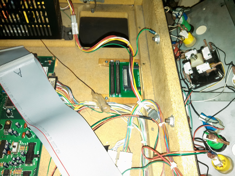
Yeah I just went to town with some nice sewing scissors.

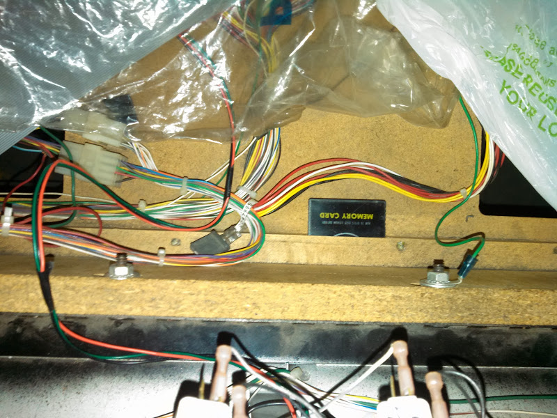
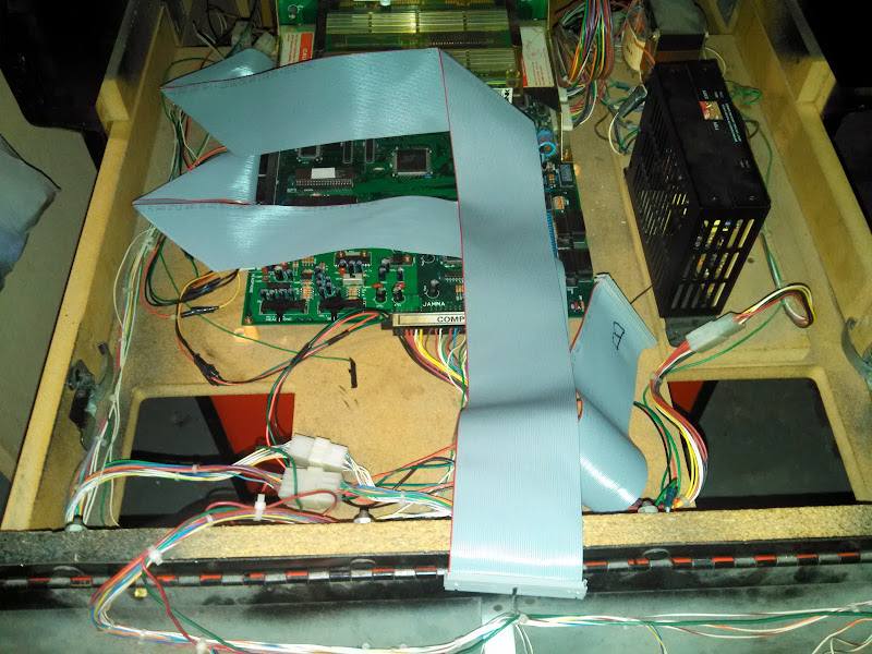
Yes you can fold ribbon cables, they're designed to do that.
What could possibly generate heat inside there? Feel free to run the cables underneath. They're plastic, they will insulate against the MVS board (well, somewhat...).
With this kind of audio connector: http://cpc.farnell.com/_/mj-073h/3-5mm-jack-sockets-stereo-panel/dp/AV15099
Hope that gives you some ideas")
")
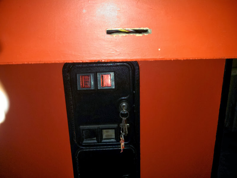
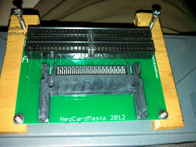


Hello all. I just became a proud owner of an MVS last Christmas. My cabinet's been converted from another game, so I don't have the headphone jacks or memory card slot either. I'd love to wire up a headphone jack too, but I don't know which pin is which. Care to share?I won't be using an MV IC, I'll be using one of NeoTurfMasta's memory card readers. As you recall, they're not going to have the headphone jacks, so mine will be wired directly to the 4-pin connector.
Hello all. I just became a proud owner of an MVS last Christmas. My cabinet's been converted from another game, so I don't have the headphone jacks or memory card slot either. I'd love to wire up a headphone jack too, but I don't know which pin is which. Care to share?
Also, I see there are 4 pins for 2 players' headphone jacks. Does that mean player 2 gets a different signal??? Interesting if true, but I can't imagine what the difference would be. I would think it'd be the same audio for both players. I suppose it could just be they use only 3 wires from a standard 4-pin connector.
This is a pretty nice forum you guys have here. I'm glad I can join the crowd.
Excellent! Thanks for the info Billkwando!Welcome, stranger.
The pinout is:
1.Left
2.Ground
3.Ground
4.Right
(same for the speaker connect)
Both players get the same signal. In the case of my hack job, I just made my own Y cable.
Oh and here's the MVS info emporium:
http://www.hardmvs.com/

 My speakers are stereo, but I'm sure my Logitec 2.1 speakers will sound better. Plus, I'll be able to mute it quickly when the phone rings.