Non Scart RGB to PVM Monitor

Gonzo

n00b
Joined
Sep 30, 2013
Posts
37
I currently own two Sony PVM's, a Genesis 1 and PS1. Am also looking at getting a Saturn and if the price is right, a MV-1 for home use (already have a cab) and go full RGB. My question is, is anybody running there console's direct to there PVM Monitors and bypassing the Scart cable? Like connecting the Genesis to straight BNC (or RCA). By what I understand there's no need to do any mods to these consoles (not like a TG-16 or SNES) to make it work with good RGB picture. Is there something in the Scart that helps or is it just for simplicity of having all the parts available? Can somebody educate me on this!:drool:
 

skate323k137

Professional College Dropout
10 Year Member
Joined
Jan 7, 2013
Posts
4,227
With the saturn I just bought a scart cable and BNC breakout. However, I have a couple consoles that I just added 4 RCA jacks to the back (R G B , Sync) and hook to my PVM using rca to bnc adaptors. It was pretty easy. I did it so I can use component video switchboxes I already had instead of getting a scart switchbox.

With Genesis I had to use some resistors/caps, with SNES just some 220uf caps. I think PS1 also needs 220uf caps too. Basically look up whatever is in the scart cable for that console. I put them inside the consoles so the signal is ready to go out of the RCA jacks.

2.jpg


4.jpg


5.jpg
 

kuze

Sultan of Slugs
10 Year Member
Joined
Apr 20, 2013
Posts
2,558
Most people use SCART cables -> BNC adapters for rgb on a PVM simply because there are common SCART cables available for most systems. It doesn't add or detract to the video quality and yeah it's all about the availability of SCART components since they have been so widely used in Europe and other parts of the world.
 

Gonzo

n00b
Joined
Sep 30, 2013
Posts
37
So Euro Scart cables DO have some kind of resistors/caps! That's what I wanted to know.

Skate323- I like how you put the RCA jacks right on the console, never thought about doing it that way! Is that the only console that you have modified that way?

Kuze- I figured it was cause it's available almost everywhere (except the U.S.of A). Am surprise I haven't seen anybody on the Retro Gaming scene custom make there own Console-to-RGB cables (BNC or RCA) and make it easy for us with PVM's.

I don't play my consoles that often, so I don't mind if I have to un-hook and re-hook cables and am also a cheap mofo!:lolz:
 

joe8

margarine sandwich
15 Year Member
Joined
Oct 25, 2007
Posts
3,753
So Euro Scart cables DO have some kind of resistors/caps! That's what I wanted to know.

Skate323- I like how you put the RCA jacks right on the console, never thought about doing it that way! Is that the only console that you have modified that way?

Kuze- I figured it was cause it's available almost everywhere (except the U.S.of A). Am surprise I haven't seen anybody on the Retro Gaming scene custom make there own Console-to-RGB cables (BNC or RCA) and make it easy for us with PVM's.

I don't play my consoles that often, so I don't mind if I have to un-hook and re-hook cables and am also a cheap mofo!:lolz:
I don't know that resistors affect the picture quality. Don't they just make it brighter or darker (ie, make the signal stronger or weaker?). So you just adjust the brightness on the monitor.
 

skate323k137

Professional College Dropout
10 Year Member
Joined
Jan 7, 2013
Posts
4,227
resistors / caps are needed for proper signal levels / brightness. It's not about quality, rather providing the monitor a signal that it's happy with and is within spec. Without resistors, the picture from a Genesis is way too bright even with brightness turned all the way down on the PVM.

I did my genesis the same way that my SNES is, with rca jacks right on the console. My superguns are the same way too.
 

joe8

margarine sandwich
15 Year Member
Joined
Oct 25, 2007
Posts
3,753
resistors / caps are needed for proper signal levels / brightness. It's not about quality, rather providing the monitor a signal that it's happy with and is within spec. Without resistors, the picture from a Genesis is way too bright even with brightness turned all the way down on the PVM.

I did my genesis the same way that my SNES is, with rca jacks right on the console. My superguns are the same way too.
But it won't actually damage the PVM (if the signal is too bright/strong)?
 

skate323k137

Professional College Dropout
10 Year Member
Joined
Jan 7, 2013
Posts
4,227
Sending a signal without the necessary caps and/or resistors could cause damage.
 

Gonzo

n00b
Joined
Sep 30, 2013
Posts
37
So by installing caps/resistors your not stressing your monitors and setting it in a more relax state were you have more adjustment.

Sounds like a weekend project. Am going to give this a try on my Genesis. I just finished opening it up and studying the Sony cxa1145 chip. Also found a decent soldering station at radio shack. this will be my first time doing something like this so i hope it works out. might even take pics. anybody got pointers to help a newbie out!
 

kuze

Sultan of Slugs
10 Year Member
Joined
Apr 20, 2013
Posts
2,558
So by installing caps/resistors your not stressing your monitors and setting it in a more relax state were you have more adjustment.

Sounds like a weekend project. Am going to give this a try on my Genesis. I just finished opening it up and studying the Sony cxa1145 chip. Also found a decent soldering station at radio shack. this will be my first time doing something like this so i hope it works out. might even take pics. anybody got pointers to help a newbie out!

If you haven't soldered before I suggest watching some YouTube videos and practicing on a crappy PCB like a broken VCR or something before you start working on your console.
 

Gonzo

n00b
Joined
Sep 30, 2013
Posts
37
the only experiance i have with soldering is on mine and my dads F-250's overhead console. stuff tends to get loose up there and then you loose your compass, outside temp and fuel to empty.
Kuze- I think ill still take your advice and practice on something old around my house cause its been about 4yrs last i did any soldering!
 

Gonzo

n00b
Joined
Sep 30, 2013
Posts
37
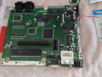
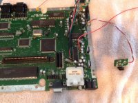
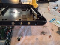
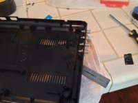
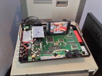
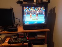
Well here's a few pics to show you guys what I've done so far.
image.jpg
image.jpg
image.jpg
image.jpg
image.jpg

It took a while for me, playing with the PVM setting to get it on RGB and I had to connect them on the RGB BNC (OUT). The screen image looks a lot cleaner and really good but for some reason it keeps climbing up and restarting from the bottom! Does anybody have a clue why it's doing that? Could it be that it's trying to read on component? Bad sync?
I had to take a break cause I really needed a cold one:lolz: I'll take a pic of what the screen looks like.
 

skate323k137

Professional College Dropout
10 Year Member
Joined
Jan 7, 2013
Posts
4,227
Sounds like a sync issue. Do you have anything on the sync line? (resistor or anything?)

Depending on the PVM model you can try composite video for sync, my 20M2MDU and 1943MD monitors happily take cvid as sync.
 

Gonzo

n00b
Joined
Sep 30, 2013
Posts
37
Yeah, it's got a 75ohm with a 220uf. Like I said the image looks really good!
I got a Sony PVM-20L2
I have Sync to #11 on the chip, C-Sync (out). Where do you think I should try, on #20 C-Video (out)
 

skate323k137

Professional College Dropout
10 Year Member
Joined
Jan 7, 2013
Posts
4,227
I tap cvid from the AV port.

I don't think sync needs the cap, maybe just the resistor alone if that. My first step would be trying to drop the cap from the sync line in your setup. Theoretically it might even need an amp, I'm not positive on that one. A quick google doesn't really help me much on that one either.

If you have an MD (medical) PVM just try cvid from the AV port. If you have an AV cable just plug that in. 20L2 might not like it though.

Sorry none of this is definitive help. Someone else might know more about it though.
 
Last edited:

Gonzo

n00b
Joined
Sep 30, 2013
Posts
37
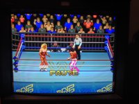
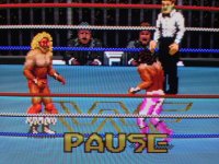
I actually went ahead and tried the easiest solution you offered first, hook up C-Video from the A/V port. The picture looks amazing!

image.jpg
image.jpg
image.jpg

It's a little late now but tomorrow, should I still drop the Capacitor from the C-Sync or just stick with the C-Video? Any pros or cons for going either way? What about the fact that am connected to BNC OUT (instead of IN)?

Skate-Before I forget I just wanted to say "Thanks" you been a big help.
 

skate323k137

Professional College Dropout
10 Year Member
Joined
Jan 7, 2013
Posts
4,227
You could try fiddling with the "clean" sync since it might clean up the picture a tiny bit. If your particular monitor accepts c-vid, and you don't notice problems, then roll with it (I know I do).

You should definitely be using the BNC INs not OUT. does it not work on the normal inputs?

Anyway, glad to help :)
 

Gonzo

n00b
Joined
Sep 30, 2013
Posts
37
Ok. So I removed the capacitor and I get the same image. I connected to RGB IN with C-Sync (also use c-video, same result) and get this picture!

image.jpg

Just a recap in case I missed something, RGB (pins 21,22,23) to 220u/75ohms, C-Sync (11) same (also tried -220u) and Ground (24) all connected to 4 RCA's

Why is it that I get a nice picture on BNC OUT with C-Video?
 

Dark Sakul

Marked Wolf
Joined
Jun 24, 2013
Posts
215
I do want to point out to future readers that Scart is not a video format, it just a type of connector wired to French/European standards.
Scart it self can carry composite, component, RGB and S-Video (although not all at the same time).
And a typical scart cable for lets say a VCR or set top Close caption box can be a 2 way transmission cable.

In the end, for your own mods it does not matter if you used RCA connectors, BNC connectors, a scart cable, a Din connector, or DB HD 15 (like what used in VGA)
Minus audio there a total of 4 signals for RGB video Red, Blue, Green and Sync (5 if you have you have sync split into vertical and horizontal)
In something like BNC or RCA connectors each signal would have their own ground, preferably in a co-axial cable.
 

Jibbajaba

Ralfredacc's Worst Nightmare
10 Year Member
Joined
Apr 30, 2009
Posts
5,611
So much more work than just buying the needed SCART cables and a SCART -> BNC breakout cable.
 

skate323k137

Professional College Dropout
10 Year Member
Joined
Jan 7, 2013
Posts
4,227
Stupid question but needs to be ruled out, you do have the negative leg of the capacitors toward the display, correct?
 

Jassin000

Frenzy Football Player
Joined
Dec 9, 2011
Posts
985
On my Genesis I'm tapping the solder joints on the bottom of the board/minidin connector. I use 100ohm resistors and 220uf caps on the RGB lines, but only a resistor on c-sync. I too must connect my sync line into "sync out" rather then "sync in" connecting to in causes the image to slowly fade out to a fully black screen.
 

Dark Sakul

Marked Wolf
Joined
Jun 24, 2013
Posts
215
So much more work than just buying the needed SCART cables and a SCART -> BNC breakout cable.

I agree, what you spend in getting the right cables you save time in headaches and time wasted ruining a perfectly good console.

On my Genesis I'm tapping the solder joints on the bottom of the board/minidin connector. I use 100ohm resistors and 220uf caps on the RGB lines, but only a resistor on c-sync. I too must connect my sync line into "sync out" rather then "sync in" connecting to in causes the image to slowly fade out to a fully black screen.
If you would get pre-made Scart cables, the resistors and caps are wired already for you.

Pay attention what version of the console you have, example European SNES consoles need resistors on the RG and B lines while the NTSC consoles needs caps.
 
Last edited:

ApolloBoy

Edo Express Delivery Guy
Joined
Feb 15, 2012
Posts
331
I agree, what you spend in getting the right cables you save time in headaches and time wasted ruining a perfectly good console.
Seconded. Plus with a SCART converter you don't have to mod every console you get with RCA jacks.
 

skate323k137

Professional College Dropout
10 Year Member
Joined
Jan 7, 2013
Posts
4,227
I agree for most users, RGB scart cable(s) / breakout cable is the way to go. I went that way with the Saturn because mine was already modded up and I don't want to tear into it.

With the Genesis and SNES I added RCA jacks for a couple reasons; I can control the quality of the components and soldering, I can use quality coaxial cables for each connection, and I can use a component video switchbox that I already had instead of buying a scart switchbox. My genesis, snes, PS2, and dreamcast are all hooked up this way (I made my own breakout box for the dreamcast out of a dead VGA box, and the PS2 is using a modified aftermarket cable).
 
Last edited:
Top