Replacing a flyback on K7000 Monitor

thieslo

Geese's Thug
10 Year Member
Joined
Nov 6, 2011
Posts
285
Hello everyone,

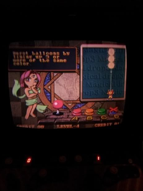
So I have a K7000 monitor that seems to be pretty dim. I have the gain on the flyback maxed, the brightness on the neckboard extension near maxed, and the screen is still dim in a normally lit room.

I have heard that with the gain maxed on flyback that I should have pretty much a green glow on my screen and then lower it.

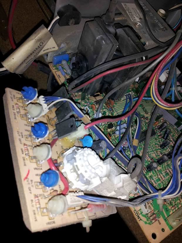
When I pulled the monitor chassis out I followed the flyback and found the black wire went into a plastic enclosure (opened it and removed the connection) and the red wire went to a little plastic housing, but I could not figure out how to disconnect it.

I also attempted to desolder the flyback, but found that I was having issues removing it so decided to just reflow new solder and leave the flyback in place.

Hooked the monitor back up after replacing all caps in the cap kit (I noticed it left 3 smallish caps unreplaced, will address later on), but the monitor's condition is unchanged.

Has anyone replaced a flyback on one of these monitors? How did you disconnect the red cable? Was the flyback easy to remove? I would rather avoid splicing the red cable if possible.

Will try to grab some pictures of the red connection i am talking about as well as the monitor.

thanks in advance for reading about my issue :)
 

thieslo

Geese's Thug
10 Year Member
Joined
Nov 6, 2011
Posts
285
Ok, let's see if I can attach photos

The two photos I have include one showing the neckboard, and in the center of the image you can see a thick red cable going into a single wire width plastic enclosure. I am unsure how to remove this cable as this is the red cable to the flyback and the plastic enclosure seems to also be glued to the neckboard in addition to being soldered. Can I slide out the red cable somehow or are my only options to cut/splice the flyback red cable or desolder the entire plastic enclosure and attempt to solder the new flyback to the neckboard?

Neckboard.jpg


This next image displays the screen after being on for a while. This is with the gain on the flyback maxed and the brightness on the neckboard extension almost maxed. It is difficult to capture just how dim it is, but I have turned off pretty much all the lights in the room to attempt a picture.

Screen.jpg


any help would be greatly appreciated :D
 

Dion

Known Scammer, NeoGeoFreak Co-Founder
Joined
Aug 24, 2000
Posts
2,070
First things first. Have you tried this chassis in another game (if possible)?

For the record the red wire has to be desoldered. The white connector is actually just a housing. The part the wire goes into opens up and then that wire gets desoldered.

What tools are you using to desolder the fly?
 

thieslo

Geese's Thug
10 Year Member
Joined
Nov 6, 2011
Posts
285
Only have the one system, monitor, and chassis, so don't have anything else to compare it to. I did do the quick short of the red/green/blue connections to see if my tube was just dim, but doing that it is very bright.

I am using a temperature controlled soldering iron and a mixture of desoldering braid and vacuum to remove the solder.

So the connector (white housing) needs to be desoldered from the bottom, then I can pull it away from the board (after removing the glue that is holding it in), then open up the housing and put the new wire inside the housing? Or is it I remove the white housing as a disconnect without desoldering and then open it up and desolder the red wire out of it?

Sorry, all I have to go off of is my personal experience and can't seem to find a youtube video (yet) that provides a close up view of this particular procedure. They usually skip past it and already have it out :)
 

malignantpoodle

Robert Garcia's Butler
Joined
Aug 21, 2010
Posts
1,281
Yeah, the colors look spot on and the saturation is very good. Probably is the flyback. I hope someone can walk you through this one I have very little experience replacing flybacks.
 

blkdog7

n00b
Joined
Oct 27, 2009
Posts
14
Your tube could also need a rejuve. It might not be the flyback.

But.. if you want to replace the flyback...

The flyback has a wire with a suction cup on one end going to the tube. It is connected to the tube. In order to remove this suction cup you need to discharge the monitor first. If you do not, you could get seriously injured. There is very high voltage under that suction cup.

There is a video on Youtube showing how to discharge a monitor here:

http://www.youtube.com/watch?v=mV9Td8vAb0Y

After that, you just pull the suction cup off the tube, there are two little metal tabs holding it to the tube. You can use a screwdriver to get it out.

AGAIN - DISCHARGE THE MONITOR FIRST OR ELSE!!!

After you discharge the tube the flyback is easy to remove by simply desoldering all the points on the chassis. Sometimes this isn't too easy as there may be trace amounts of solder left and the thing just wont come off. There also are going to be some other wires. Just pay attention to what they are and connect the new flyback the same way.
 

Dion

Known Scammer, NeoGeoFreak Co-Founder
Joined
Aug 24, 2000
Posts
2,070
So the connector (white housing) needs to be desoldered from the bottom, then I can pull it away from the board (after removing the glue that is holding it in), then open up the housing and put the new wire inside the housing? Or is it I remove the white housing as a disconnect without desoldering and then open it up and desolder the red wire out of it?

No. Don't desolder the socket. The housing opens up to reveal the wire to desolder. Pic below:

24g7tbl.jpg
 

BlueBMW

New Challenger
Joined
Jul 18, 2011
Posts
65
I had a similar issue with my WG K7000, I did a full recap plus new fly back and it came back to life. My tube was burnt to hell and back so I ended up replacing it as well. If you havent recapped the chassis yet, do so! I got a cap / flyback kit from bob roberts. It was missing the large input filter cap and the three 10uf non polar caps so I had to source those separately.

My resto / rebuild was somewhat detailed in this thread:

http://www.neo-geo.com/forums/showthread.php?227370-My-First-Neo-Cab!&daysprune=365
 

jetblue

Crossed Swords Squire
Joined
May 6, 2006
Posts
185
very nice bmw,how long did your restoration take or is it still going on?
 

BlueBMW

New Challenger
Joined
Jul 18, 2011
Posts
65
Its basically done for now. Only thing left to do is replace the capacitor for horizontal picture size since the adjustment coil doesnt have enough range to get the picture just right.

OP, let us know how the flyback replacement goes. But again, if youve already got the chassis out, it'd be best to go ahead and do all the caps.
 

thieslo

Geese's Thug
10 Year Member
Joined
Nov 6, 2011
Posts
285
Wow, I hadn't checked this thread for a few days and lots of new posts :D Thank you everyone.

Mitsrurugi, the black wire to the flyback isn't the one I am referring to. I am able to open up the enclosure and pull the wire out without any desoldering. The red cable is the one I am talking about. This weekend hopefully I will try again to remove it, if I cant seem to remove it, then I will splice the new flyback onto it, after desoldering the main component from the chassis.

blkdog, I have completely removed the chassis from my cab earlier this week, including the suction anode, desoldered the ground off the neckboard. The only piece connecting the neckboard to the chassis now is the single red cable that links the flyback to the chassis.

bluebmw, I noticed that with my cap kit as well. There seemed to be 3 caps my cap kit didn't have in it. I replaced all other caps already and it seems to be working fine. However, no change in picture whatsoever. At least it is playable :)

I am hoping to get to it this weekend if possible, but it will depend on my schedule. I will post a result picture once I get everything taken care of and put back together :)

Thanks again for everyone's help.
 

FA-MAS

Kula's Candy
Joined
Oct 3, 2009
Posts
299
I'd say don't splice anything when it comes to a flyback, you're dealing with really high voltage. That red cable is just a single pin connector, it should just slide right off the pin on the board. It looks like yours is glued though. I'd see if you can chip away at the glue.
 

Dion

Known Scammer, NeoGeoFreak Co-Founder
Joined
Aug 24, 2000
Posts
2,070
Yeah. FA-MAS is right. I thought you were talking about the other wire. Someone glued it down for some reason. You'll have to find a way to get through that glue.
 

thieslo

Geese's Thug
10 Year Member
Joined
Nov 6, 2011
Posts
285
Ok, going to post an update. I have replaced the Flyback. I chipped away at the glue and finally got a big chunk off and the housing complete with cable slid right off. Pulled the red cable out and shoved mine in. Probably not the best (should probably invest in a molex pin extractor), but it seems to work.

The hardest problem I had this time around was actually getting the flyback to fit back into the chassis. The pins on the old flyback seemed to be bent ever so slightly so it was hard to line up. My abilities in desoldering are much better and I had no problem clearing off all of the solder.

Once the flyback was in and I fired up the machine I had my wife watch as I slowly upped the gain and focus. It isn't green bright (I think those three caps will need to be replaced that didn't come in the cap kit, but will look into that later, but it is quite a bit brighter than before.

Here are the two comparisons
Screen.jpg

screen_new_flyback.jpg


I tried to get the same image and this time my flyback is only set at maybe 75% of max. I would label this a success. Now to work on more cosmetics on the cabinet :D

The one sad part, while removing the neckboard from the yoke part of the plastic on the yoke came off with it as well :( I need to be really careful on that yoke now as it is just pure glass and wires. The plastic piece that fell off was very brittle even once in my hands. I guess that is what I get for buying a 20 year old machine, huh?

Thank you everyone for your help and advice :D
 

malignantpoodle

Robert Garcia's Butler
Joined
Aug 21, 2010
Posts
1,281
Yeah that is a lot better. Still not ideal but a huge improvement.

Did you replace EVERY cap on the chassis?

You might also try leaving it on for several hours and see if the image gets better. If over that much time it does, then you know it's a cap issue.
 

thieslo

Geese's Thug
10 Year Member
Joined
Nov 6, 2011
Posts
285
Wife is playing it at the moment, but it seems to be staying about the same. There were 3 caps I noticed on the chassis that the cap kit I purchased did not replace. They were 25V 10uF caps all three in a nice line. They are actually in the bottom right corner of my first picture. I am probably going to look for some additional caps but right now I am pleased with the way it looks.

I will let you know how it goes, one issue I forgot because I bypassed is my sound issue :D still a lot of cosmetics to work on.

My sound issue is just funny, it makes a loud clicking noise. Very annoying and painful at times. However, my work around is to disconnect my speakers and wire up my own external speakers to one of the headphone jacks. For some reason, both headphone jacks produce sound just fine, and the sound issue only happens on occassion (and always on start up).
 

malignantpoodle

Robert Garcia's Butler
Joined
Aug 21, 2010
Posts
1,281
Here is a comparison of my screens. When you're working with one cab/screen it's hard to see how it stacks up.

The first here is a brand new (well, about 3 weeks old) Makvision monitor from Suzo Happ. It's a new monitor and I've never made any adjustment to it at all.
screencompare2.jpg


Next up is a Sony PVM 2030 monitor running on Svideo from a consolized MVS.
screencompare3.jpg


Last but not least, and more relevant for comparison is the first screen I got in a junked cab. It is a Kortek that is 22 years old. I have replaced all of the caps except for three power caps that have unusual specs. I haven't bothered to order them for replacement but will get around to it. I also had to repair several traces and reflow solder joints on the RGB and remote board pins. This screen was on the brink of death and unplayable. It looked worse than yours before the flyback change and only displayed blue color which could barely be seen;
screencompare1.jpg


Bear in mind these are crappy cell phone pics. The last monitor is given much more brightness than it really appears to have. But if you don't look at the other screens in person, it looks just fine. However if you play on the cab with the new monitor for 20 minutes then switch over, there is a big noticeable difference.

Hopefully that gives you an idea of what's out there and what you're shooting for.

The sound issue is probably just caps in the audio section. I have replaced caps in every MVS board I've had and every one needed it. Even one where the sound seemed, "perfect", I replaced caps anyway and BAM it got a lot louder and cleaner.
 
Last edited:
Top